Waunakee Innovation Center
Machines that Make
This is our group project Pen Plotter
Mechanical Design Week 9
Assignment:
Group: Design a machine (Mechanism + Automation)
Including the end effector. Build the passive parts and operate manually.
The Machine
As a group from the Waunakee Innovation Center (Fab Lab Waunakee) we talked about many different machine ideas. We arrived on a CNC type machine that would be used to draw on paper. We wanted to incorporate all 4 motors to make sure the machine could use the X, Y, and Z axis. We were also taking design into consideration due to the fact that I am an art teacher and Jeff is technology engineering, we take pride in how our projects look.
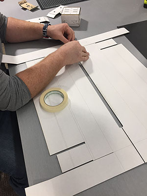
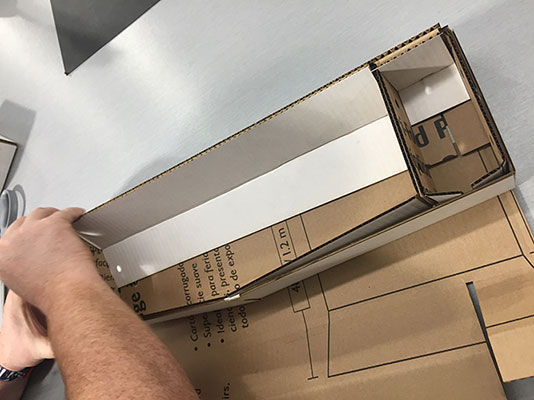
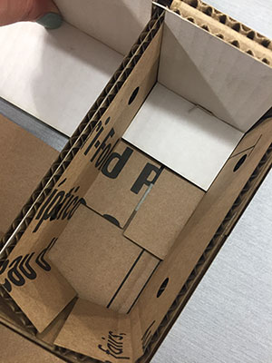
Our first step was to create the box that surrounded the motor. We went to the [modular] Machines that make: cardboard stages page to get a grasp of the concept. We followed their directions for the enclosure to the motor and box to create the X and Y axis. http://mtm.cba.mit.edu/machines/science/
Once we made our first box out of cardboard we realized that this wasn’t quite the design or the quality that we wanted our finished project made out of.

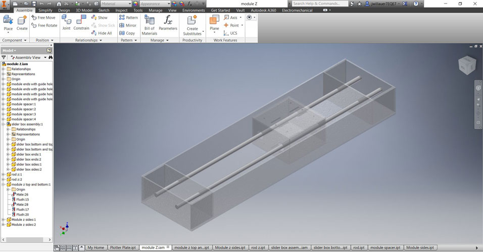
So we went back to the drawing board. Literally. We modeled our Machine that Makes in Inventor so that there was an X, Y, and Z.
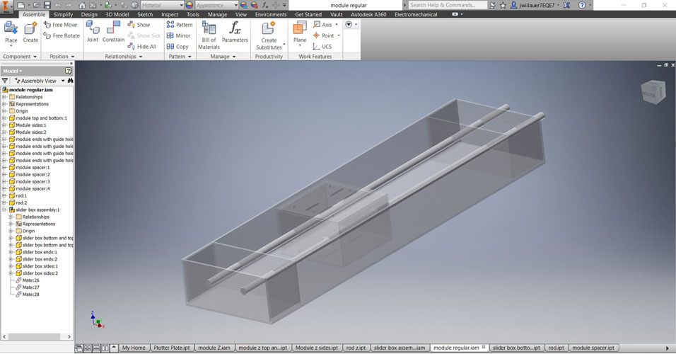
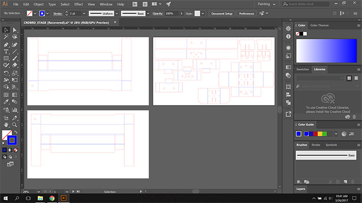
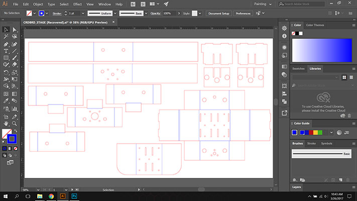
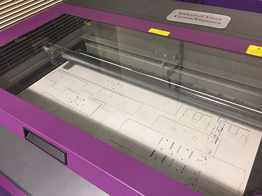
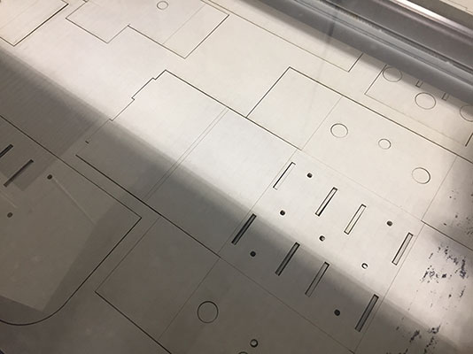
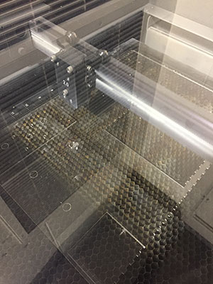
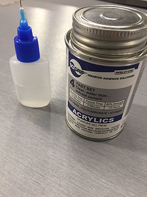
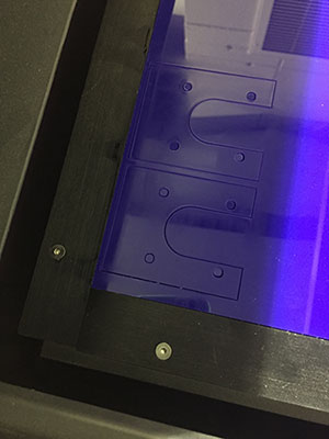
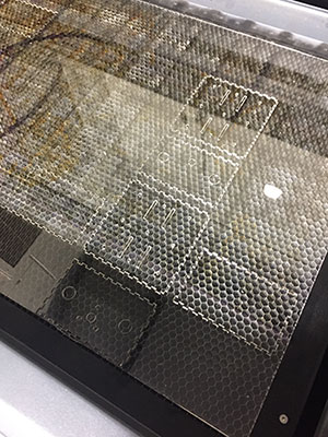
We used Illustrator to create the outlines of the box and used the laser to cut them out. We decided that press fit acrylic would suit our design and functionality needs and we used an acrylic adhesive that actually melts the two pieces of acrylic together. As we built we changed the accent colors to create a more interesting feel. We used .085” clear acrylic and .15” opaque blue acrylic.
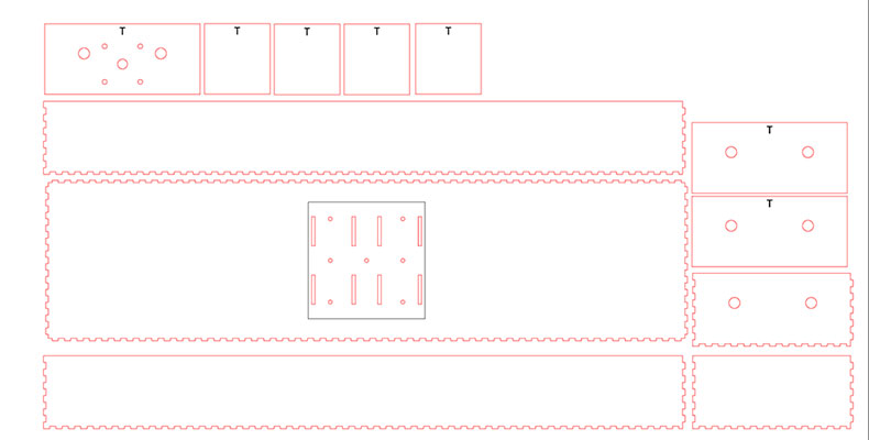
Main box layout in Illustrator ready for the laser.
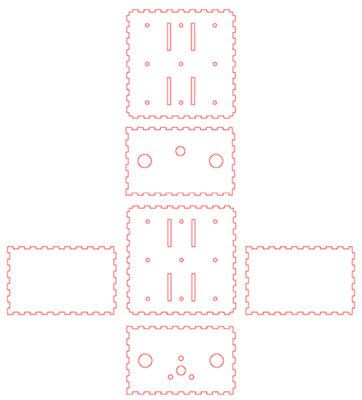
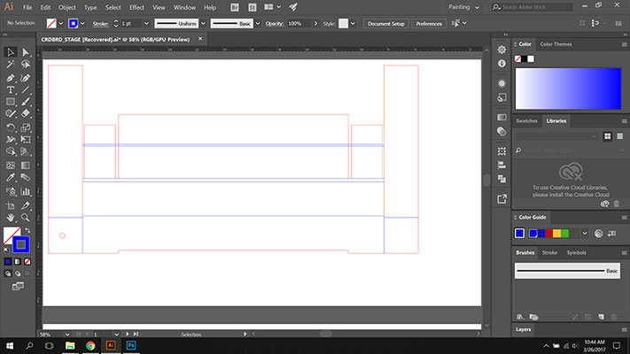
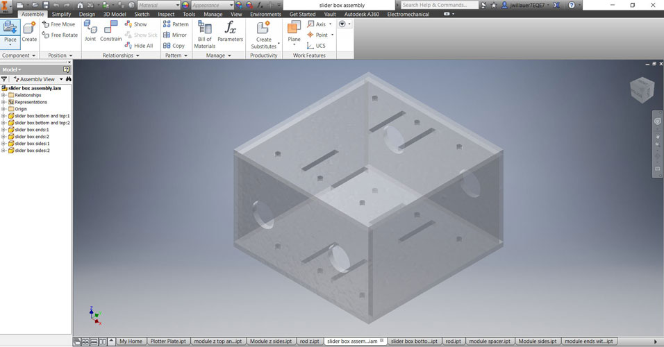
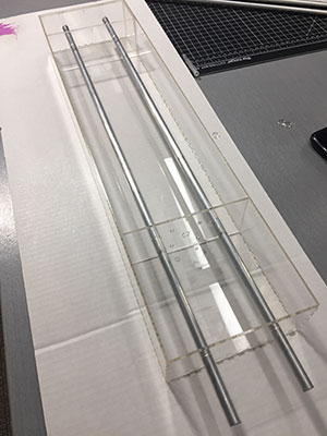
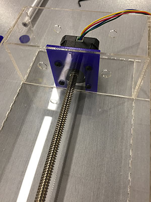
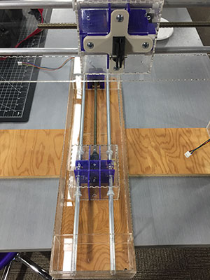
Middle box that moves along the stepper motor.
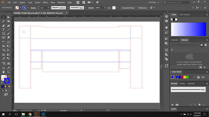
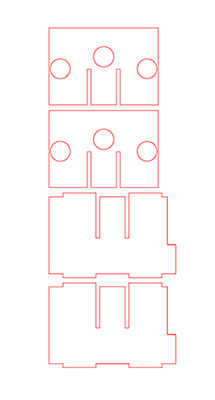
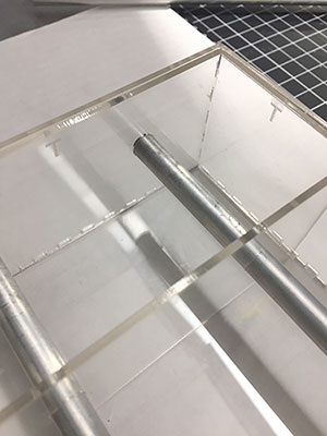
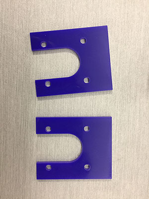
Pieces to hold the motor back from the plate infront of it.
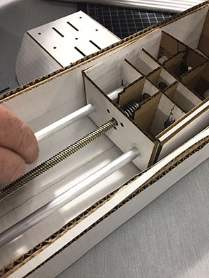
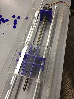
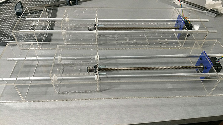
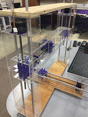
The box that we created for the Y was a normal box with holes on the bottom so that we could mount it to a bottom plate for the whole machine. We created an X axis that had holes to match the 2 Z axis boxes to move along the stepper motor. As one of us designed the other put the pieces together and started thinking about the Z axis. Our next design choice was to use 2 more motors to create the Z axis to raise and lower our drawing tool. So we created 2 more boxes.
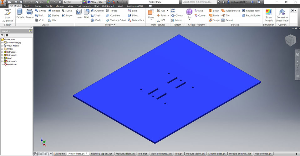
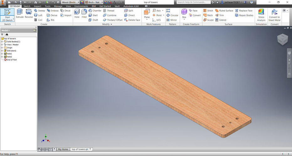
The base and the top pieces of the machine are made from .5” plywood. These pieces were designed in Inventor and then imported to Fusion 360 and cut on our CNC router.
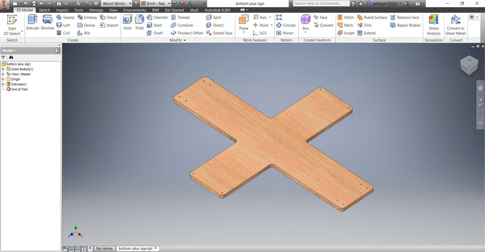
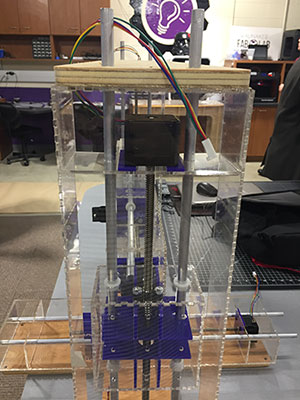
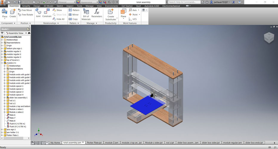
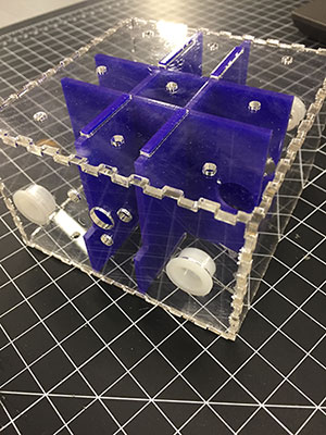
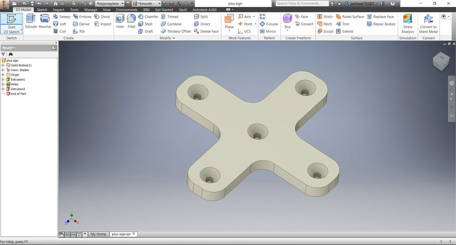
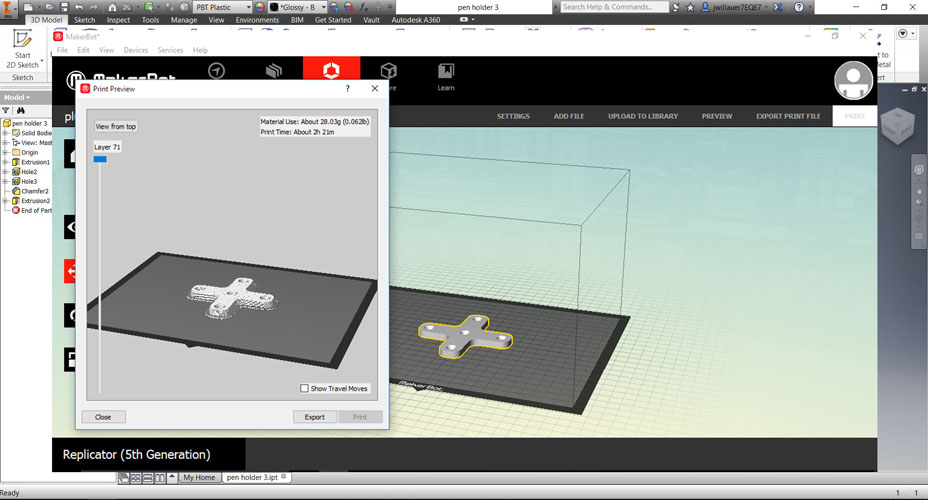
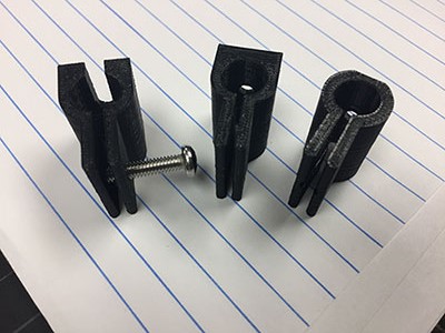
The last design choice we made was to create the holder for the pen. This was also designed in Inventor, but then printed on our Makerbot 3D printer. This took a few tries and there were 3 different prototypes made to work with the box that is driven by the motor. It is a two piece part, the plus sign on the back and then the pen holder with a screw to secure the pen.
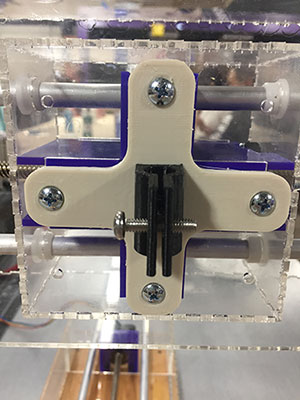
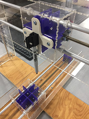
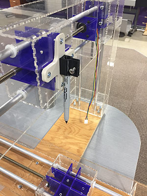
The machine successfully operates on the X, Y, and Z axis. We can manually move the motors in all directions operating the pen to create a drawing.
Machanical Design Week 11
Week 11:
Machine Design
Assignment:
Automate your machine. Document the group project & your individual contribution.
Machine: Sensing & actuation
Input: Sensor, Actuators
Stepper Motors: Measure position
Static: Consistent
Dynamic: Machine that bends and forms
PID: Proportional Integral Derivative. One input where you are now, the other where you want to be.
How to tell the Machine what do to:
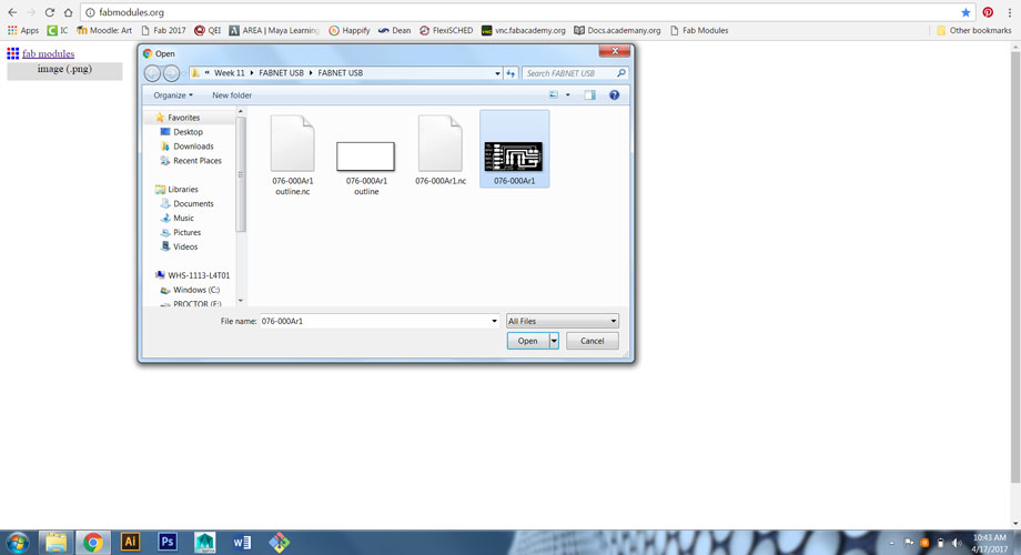
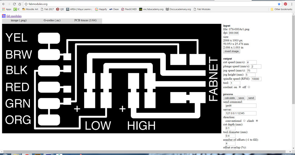
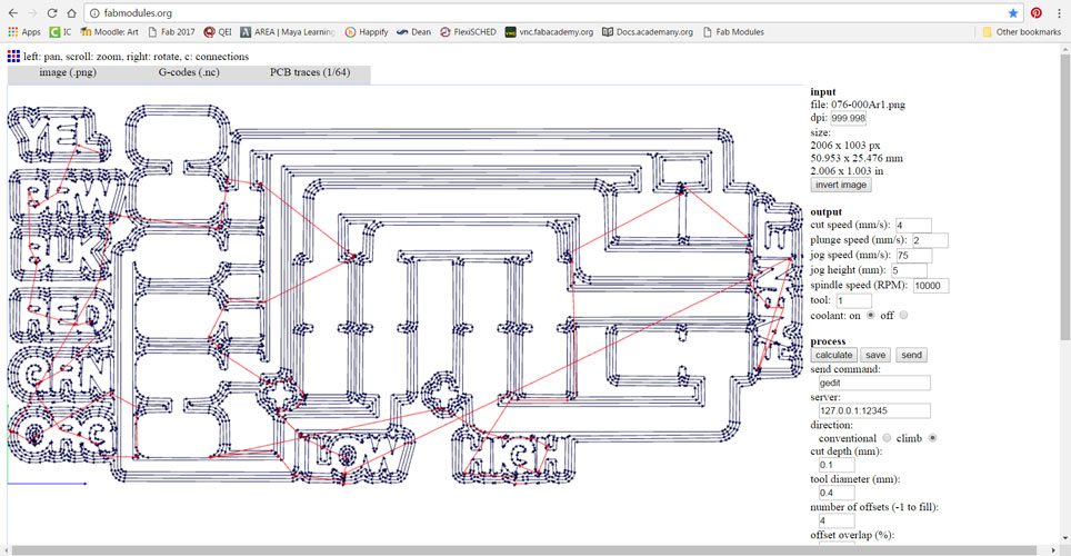
G-codes: Were used by early photo plotters. Series of letters followed by numbers. No universal g-codes. Most common and what we used in Fab Mods.
Hpgl: Bracket plotters. Some milling/lasers use this.
OpenSBP: Shop Bot format.
TinyG: AVR processes-board that includes the interpreter for the file. Stepper motor controllers & loop in software. Docs has files.
Programming/Linus/Gestalt/Python/Pyserial/FabNet Board - All of this!:
I started this week by looking at length at the documents that were on Machines that Make to help understand the process. The following links were some of the places that I looked:
http://archive.monograph.io/james/m-mtm
http://mtm.cba.mit.edu/machines/science/
http://fabacademy.org/archives/2015/doc/MachineMakingNotes.html
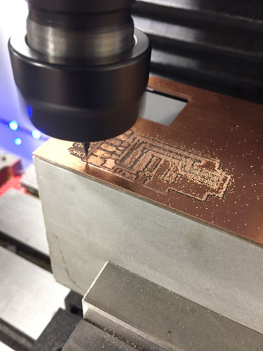
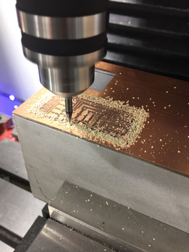
I learned that no matter what meathod we chose, we would need the FABNET board so it was off to the mill, warmed up my soldering iron and made a bunch of 10pos ribbon cables.
Once I finished with my research I jumped in on my Terminal.
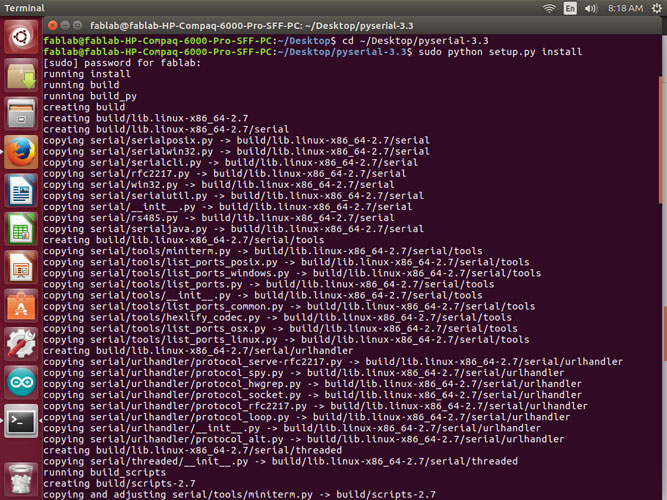
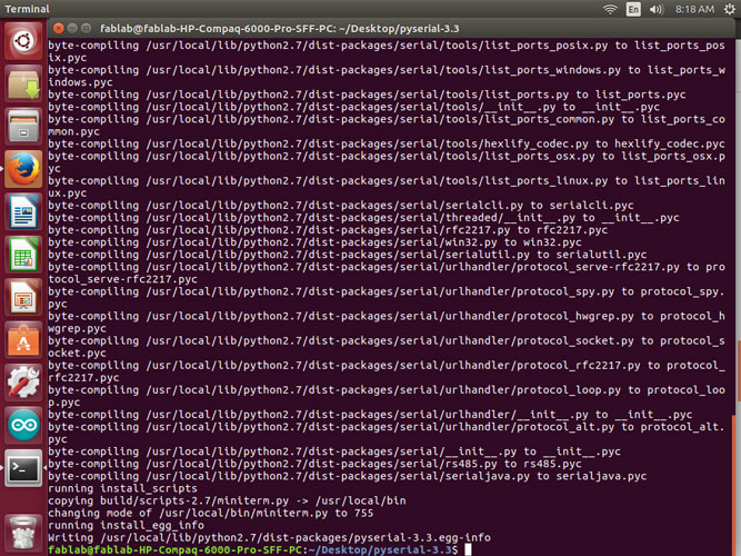
I downloaded pyserial 3.3, unzipped and installed it.
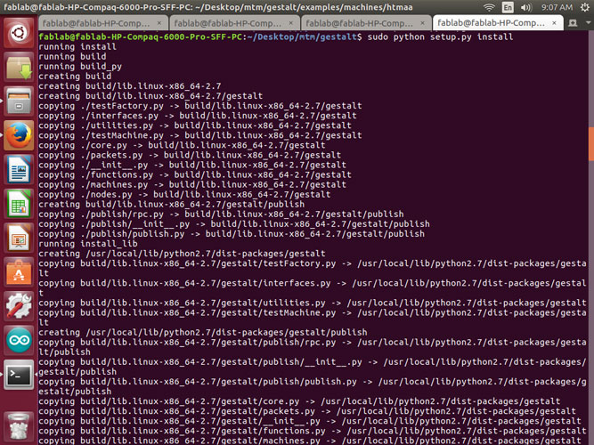
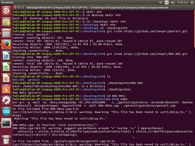
I created a directory for where I wanted my makefile and gestalt to be. I downloaded the correct library from Github for Gestalt and installed it.
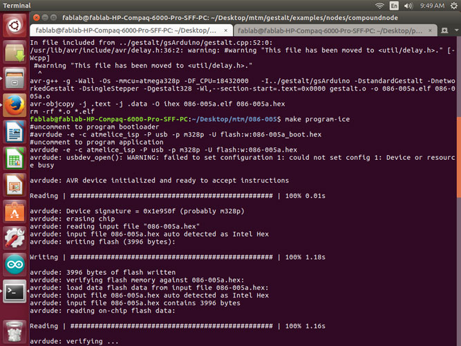
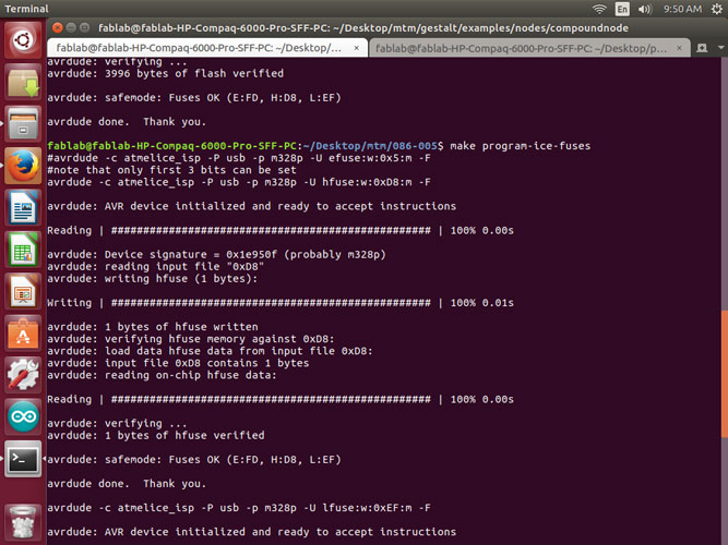
I then cd’d into the folder where the make file was placed and then ran the make file for the gestalt board with the correct language for the Atmel_Ice.
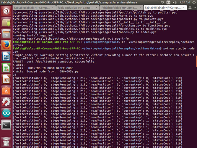
Then I cd’d into the folder where the single_node.py file was located to test the axis and connection.
I received multiple different situations along the way.
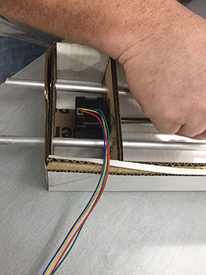
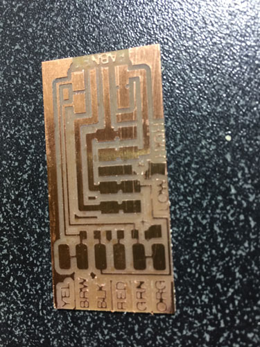
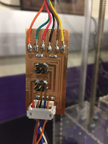
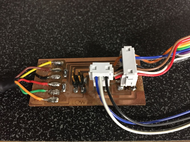
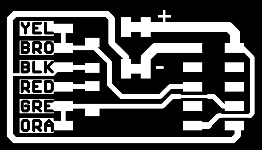
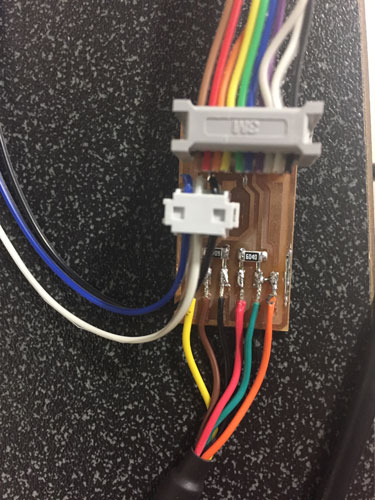
I double checked my connection on the FABNET 8pos cable to make sure the GND's were in the right place along with the High V and 7.5 V. My pinout is below:
1-Red 2-White (High V) 3-Brown 4-Black (GNG) 5-Empty 6-Empty 7-Blue 8-Orange (RS-485A)
I Also checked the other end of the cable to make sure that the 10pos was correct.
I opened the Makefile I was using to flash your board and checked to make sure the 'bootloader' code is commented and the 'application' is uncommented. It looked like this:
#bootloader
#PROJECT = 086-005a_boot
#ADDRESS = 0x7000
#GESTALT_DEFS = -DstandardGestalt -Dbootloader -DsingleStepper -Dgestalt328 -DnetworkedGestalt
#application program, uncomment if you want to use this instead.
PROJECT = 086-005a
ADDRESS = 0x0000
GESTALT_DEFS = -DstandardGestalt -DnetworkedGestalt -DsingleStepper -Dgestalt328
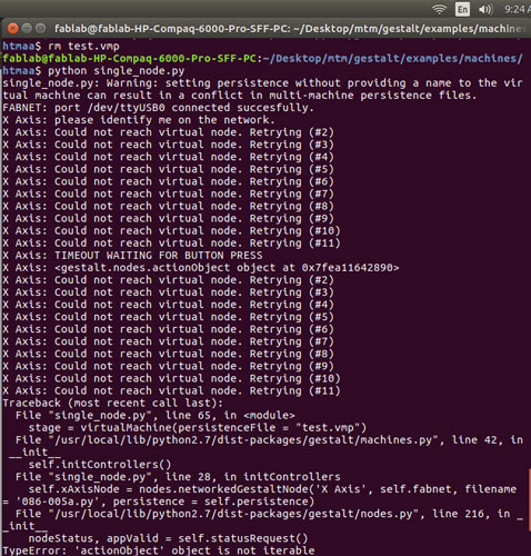
I deleted the file 'test.vmp' and rand the python program again. I also tried reflashing the node. Making sure I used the correct Makefile.
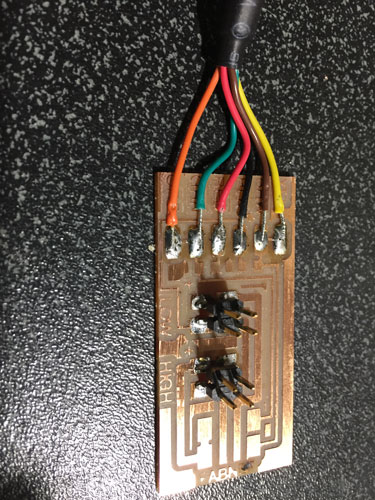
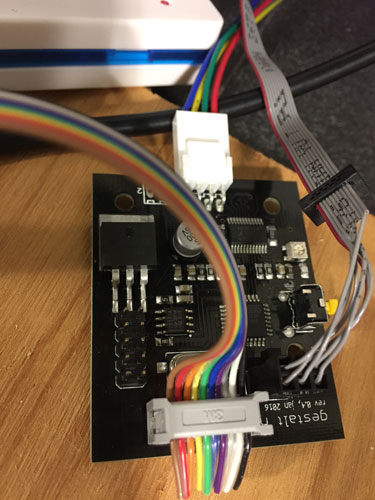
Once none of that would work and it was still running in bootloader mode. I decided to make the new FABNET board.
http://mtm.cba.mit.edu/fabinabox/dev/fabnet/overview.html
http://mtm.cba.mit.edu/fabinabox/dev/fabnet/files.html
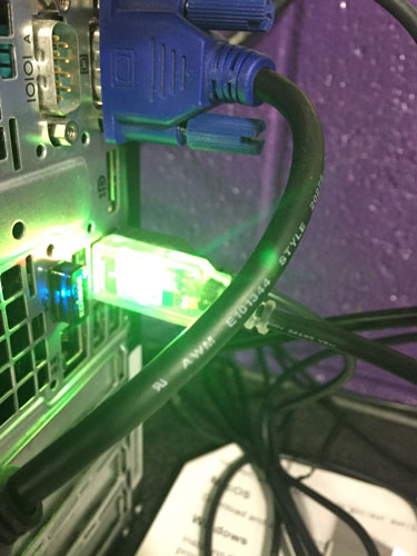
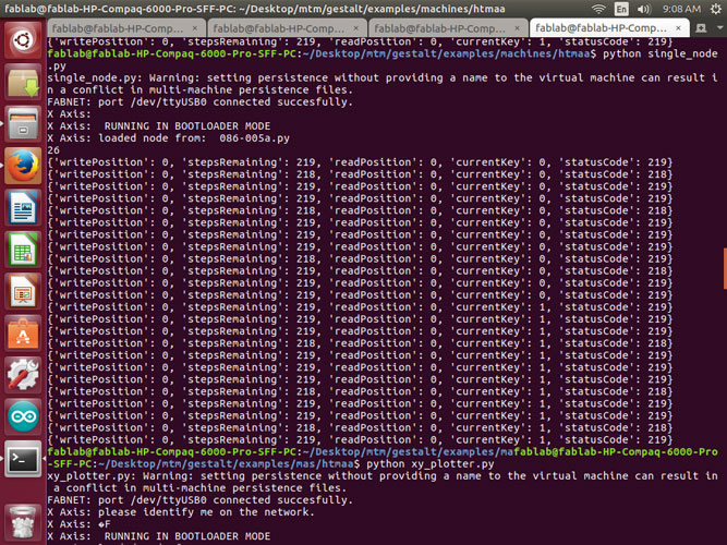
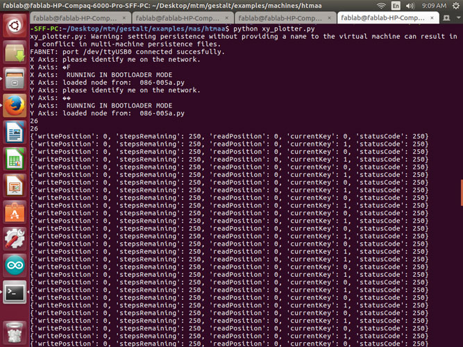
This used the ribbon cable that runs straight through. We tested the power to make sure we had our positive and negative pinouts in the right direction. Once I ran the single node again, this is what I got. We ran the single_node.py multiple times, one attempt we did get the blue light to blink (Click here for video) on the board, but the terminal still said it could not reach the virtual node.
This is where our progress is! We have tried a million things. If anyone has any ideas please help!